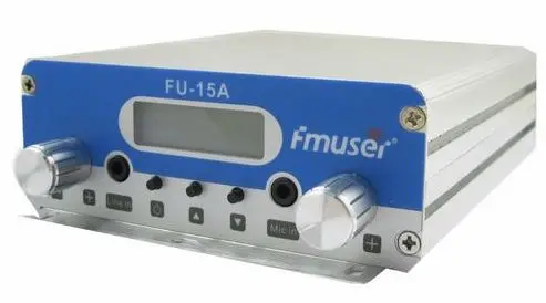
2 Km Fm Transmitter
With the help of such FM transmitters we can easily transmit the audio signals through the carrier waves with different frequencies. The frequency of the carrier wave would be the same as for the audio signal with an amplitude. The FM Transmitter produces a range of VHF from 88 HZ to 108 MHZ. Block Diagram for FM transmitter circuit Components required for FM transmitter circuit are modulator, oscillator, RF-Amplifier, Audio pre-amplifier, microphone and antenna. The Diagram shows the Block diagram for FM transmitter circuit. There are two types of frequency in the signal: Carrier signal (with carrier frequency) Audio signal (With audio frequency) FM transmitter circuit Block diagram The carrier frequency is obtained by modulating the audio signals. The (Frequency Modulation) FM signal is obtained by differentiating the carrier frequency and by allowing the Audio frequency. The transistor is used for oscillator purpose in order to obtain Radio Frequency signal. Working of simple FM Transmitter Circuit explanation The circuit diagram shown for FM transmitter circuit and the electronic components are the resistor, capacitor, trimmer or variable capacitor, inductor (coil), transmitter, mic, 9v of power supply or 7809 Voltage regulator (in case if you are using input voltage more than 9v) and an antenna.
How to Make a 2 Mile, Long Range FM Transmitter Part 1 : 4 Steps - Instructables


You can explore the various ranges of 20km fm transmitter at that are useful in performing residential broadband services, telephone operations, television functions, networking activities and other private network applications. The engineered fiber routing of these 20km fm transmitter aid in protecting the bend radius of the unit to ensure seamless signals. These 20km fm transmitter are compatible with pole-mount, wall-mount, and flush-mount outlets, among others. The wide range of 20km fm transmitter options at can help you save loads of money on the purchases. These items can find applications in WAN, MAN, FTTH, LAN, PON and VLAN. You can place OEM orders for bulk purchase and customized packaging too.
Moreover please note that the pin configurations are different for these 2 types. In case TO92 pack is used then increase the value of R7 to 56 ohms 1/2 watt failing which it shall burn. But this TO92 pack may affect the range Q3 has to be 2N3866 with a heat sink for proper range. However 2N 2219 can be used that will but compromise the range drastically Step 3: Testing Initially use a simple 75CM single wire standing straight as antenna for getting a range of about 100-200 meters indoor. Similar length telescopic antenna is also OK for testing which will give only about 100-200 meters range. But never go longer than 79 CM antenna wire thinking that it will cover higher range. In fact if you do so the range will fall. Frequency of the transmitter can be set with in 88 to 108 MHz FM band by adjusting the TR1 (Trimmer 1) of the VFO or by changing the spacing between the Coil L1. 1 Frequency Adjustment: NOTE: Don't try to test the unit in evening to night because at that time many powerful FM stations will be active.
- Ensayo La Vida Es Bella
- Titanic descarga directa
- How to make FM transmitter circuit with 3 km Range
- Giochi Playstation 4 – FULL ITA – Direct Download | VictorHacking - Hacking, Console, PC e molto altro ancora!
- How to Make a 2 Mile, Long Range FM Transmitter Part 1 : 4 Steps - Instructables
- 2 km fm transmitted diseases
- Amazon.com: The Irish DADGAD Guitar Book (0752187441472): McQuaid, Sarah: Books
With a matching antenna, the FM transmitter circuit shown here can transmit signals up to 2 kilometers. The transistor Q1 and Q2 forms a classic high sensitive preamplifier stage. The audio signal to be transmitted is coupled to the base of Q1 through capacitor C2. R1, R3, R4, R6, R5 and R9 are the biasing resistors for the preamplifier stage comprising of Q1 and Q2. Transistor Q3 performs the collective job of oscillator, mixer and final power amplifier. C9 and L1 forms the tank circuit which is essential for creating oscillations. Inductor L2 couples the FM signal to the antenna. Notes: - Assemble the circuit on a good quality PCB. - The circuit can be powered from anything between 9 to 24V DC. - Inductor L3 can be a VK220J type RFC. - For L1 make 3 turns of 1mm enamelled copper wire on a 10mm diameter plastic former. On the same core make 2 turns of 1 mm enamelled copper wire close to L1 and that will be L2. - Frequency can be adjusted by varying C9. - R9 can be used to adjust the gain.
Frequency can be adjusted by varying C9. R9 can be used to adjust the gain. For optimum performance, value of C8 must be also adjusted. Using a battery for powering the circuit will reduce noise. Read more: Under Creative Commons License: Attribution
If it gets heated up badly switch off and reduce the current. Important Note:-(Don't use a metallic screw driver have to use a small piece non iron metallic object to work as a screwdriver - this will not alter the frequency while you take your hand near or away from the trimmer that usually happens in a metallic one) or aluminum screw driver with insulated top is preferred. Step 4: For Long Range For Long Range use a Yagi antenna The output is fed to a coaxial cable (generally used for cable TV) which is nearly matched to the Yagi antenna (though 300 Ohms) impedance of 75 ohms by trimmer TR 2 of the tuned circuit for maximum power delivery to the load ie the Yagi / GP antenna. Transmitter should never be powered without the antenna (ie the load) in which case the total power forms a SWR standing wave ratio on the power transistor Q3 heating it up badly to result in failure. DESIGN OF YAGI UDA ANTENNA: (YAGI ANTENNA) Refer my details elsewhere on my postings or here Be the First to Share Recommendations
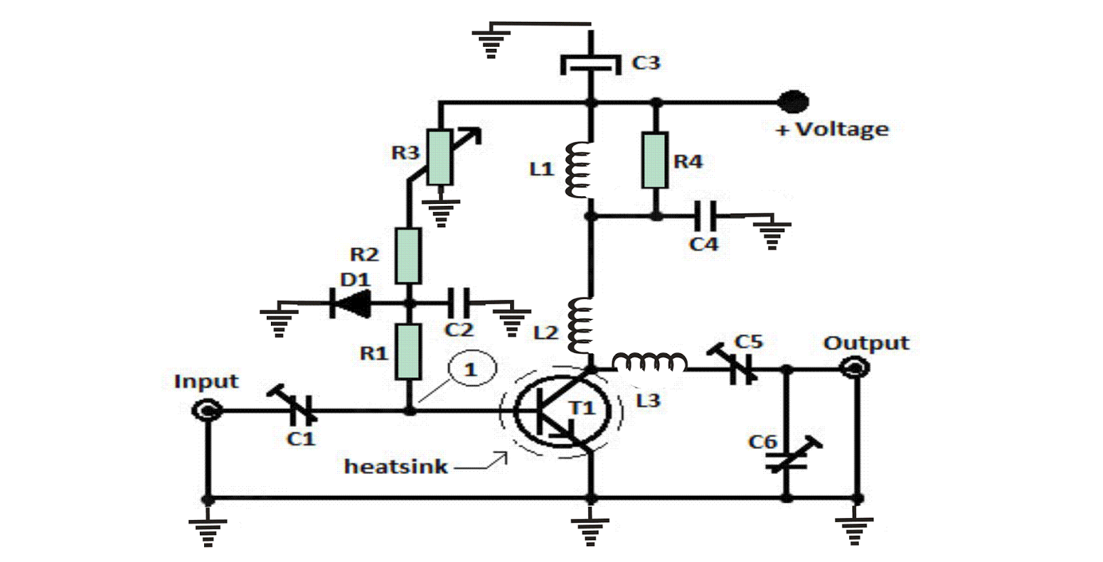
Above circuit gives the very high efficiency in transmitting signal in a shorter range. The circuit is best suited for demonstration and fm transmitter circuit project. The circuit does have a large and complicated components. The transmitter circuit is capable to neglect the noise signal through the amplitude variation. Disadvantages of FM Transmitter Circuit In above FM Transmitter Circuit, there is a large wider channel needed. With the Circuit, the transmitter as well as the receiver tends to become more difficult. The received signal gets poor quality as there an interference occurs in the medium. The above circuit is not good enough for high power fm transmitter circuit purpose. After making the FM Transmitter Circuit you will be able to understand the basic working and application of the transmitter. Hope the article helped you. Feel free to share about how do you like or your queries in a comment below. Combine Creativity & Create a Circuit just like you do in real. Empower Your Circuit Designing Skill with Virtual Lab, Today!
USB IO Board USB IO Board is a tiny spectacular little development board / parallel port replacement featuring PIC18F2455/PIC18F2550 microcontroller. USB IO Board is compatible with Windows / Mac OSX / Linux computers. When attached to Windows IO board will show up as RS232 COM port. You can control 16 individual microcontroller I/O pins by sending simple serial commands. USB IO Board is self-powered by USB port and can provide up to 500mA for electronic projects. USB IO Board is breadboard compatible. ESR Meter / Capacitance / Inductance / Transistor Tester Kit ESR Meter kit is an amazing multimeter that measures ESR values, capacitance (100pF - 20, 000uF), inductance, resistance (0. 1 Ohm - 20 MOhm), tests many different types of transistors such as NPN, PNP, FETs, MOSFETs, Thyristors, SCRs, Triacs and many types of diodes. It also analyzes transistor's characteristics such as voltage and gain. It is an irreplaceable tool for troubleshooting and repairing electronic equipment by determining performance and health of electrolytic capacitors.
After that get back on the very first trimmer and readjust yet again until you receive the maximum voltage on the multimeter. For one watt rf power you could possibly ascertain a twelve to sixteen Voltage. The method is P (in watt) is equivalent to U2 / Z, wherein Z is 150 for 75Ω resistor or 100 for 50Ω resistor, nevertheless one should keep in mind that the proper rf power is lesser. After those modification, in case things are heading nicely hook up the antenna, keep on employing the rf probe, readjust once more all of the the trimmers right from T3. Guarantee you don't have harmonics, verify the TV and radio set to determine if there exists fluctuations on the band. Verify this in an alternative area, a long way away from the fm transmitter or antenna. The unit is all set up to be used for exchanging music, talks, chats across the suggested range and bands. Circuit Diagram All Inductors are air cored L1 = 5 wounds / 23 SWG / 4mm silvered copper L2 = 6 wounds / 21 SWG / 6mm enamelled copper L3 = 3 wounds / 19 SWG / 7mm silvered copper L4 = 6 wounds / 19 SWG / 6mm enamelled copper L5 = 4 wounds / 19 SWG / 7mm silvered copper T1 = T2 = T3 = T4 = BF199 T5 = 2N3866 for 1Watt / 2SC1971, BLY81, or 2N3553 for 1.